Logic gates are the elementary building blocks of digital circuits. They receive one or more inputs interpreted as logical 0 and 1 and produce an output according to a precise rule. By combining gates, engineers can compare data, make decisions, add numbers, select signals and build more complex structures such as registers, memories and arithmetic logic units.
Intel describes the hierarchy of a modern chip clearly: transistors form logic gates; gates form circuits; circuits form processors containing millions or billions of transistors. Learning AND, OR and NOT therefore means studying the first organised level at which simple electrical states become computation.
What do 0 and 1 really mean?
NIST defines a bit as a binary digit with the value 0 or 1. In a logic diagram, these are abstract states. They may mean false and true, low and high, disabled and enabled, or any other pair of conditions defined by the design.
It is convenient to imagine 0 as the absence and 1 as the presence of a condition, but this is not a universal physical law. Real circuits represent both values with voltage ranges determined by the logic family, supply voltage and input thresholds. Logical 0 does not always mean zero volts, and logical 1 has no single voltage valid for every device.
Truth tables: listing every possible answer
A truth table lists every input combination and the output produced by a gate. One input gives two combinations. Two inputs give four: 00, 01, 10 and 11. In general, a complete table for n inputs has 2ⁿ rows.
A and B usually label inputs, while Y or Q labels the output. The table does not describe the internal transistor circuit; it specifies the logical behaviour that the device must implement.
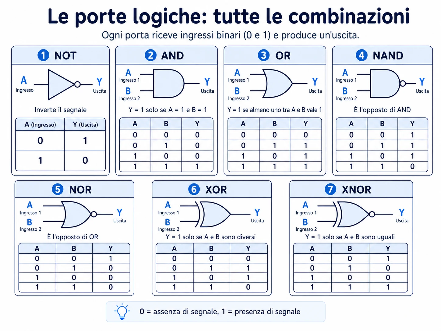 Seven fundamental logic functions compared through symbols, rules and every two-input combination.
NOT: the inverter
NOT has one input and always produces the opposite value:
- if A = 0, Y = 1;
- if A = 1, Y = 0.
The function may be written as Y = NOT A, Y = ¬A or with an overline above A. In the conventional ANSI/IEEE symbol, the triangle points towards the output; the small circle, often called an inversion bubble, is the feature that explicitly marks negation.
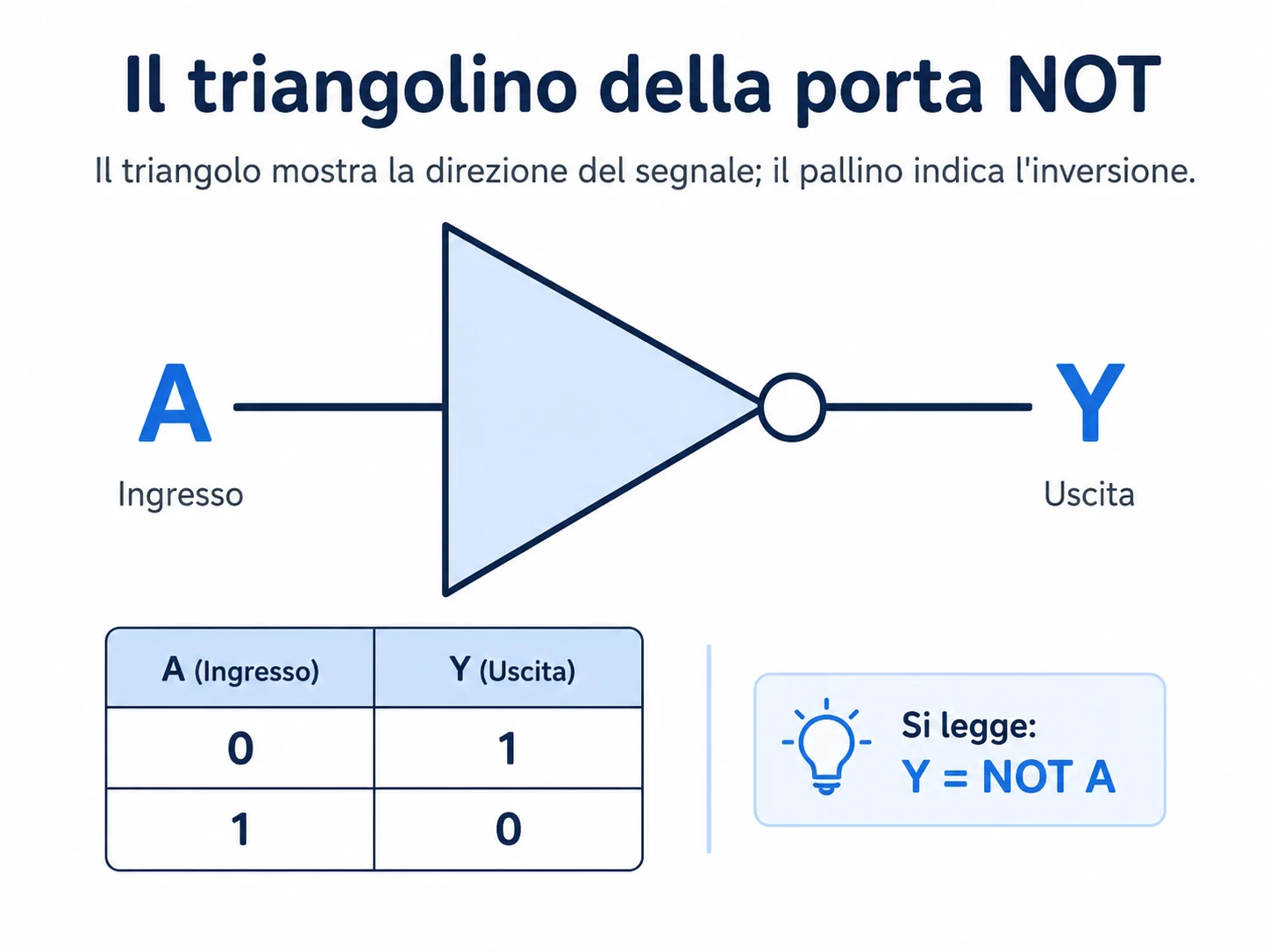 The output bubble indicates inversion: 0 becomes 1 and 1 becomes 0.
An inverter can convert an active-high signal into an active-low signal, generate a bit's complement or adapt the polarity of a control. A bubble may also appear on inputs or outputs of other symbols and always indicates negation or active-low behaviour.
AND: every condition must be true
A two-input AND gate produces 1 only when both A and B are 1:
Y = A AND B
It expresses “all required conditions”. A machine may run only if the start command is active and a safety guard is closed. Data may pass only if it is present and an enable signal is asserted.
Boolean algebra often writes AND with a dot, implicit multiplication or ∧: Y = A · B. It is not ordinary arithmetic multiplication, although the one-bit results happen to match 0 × 0, 0 × 1 and 1 × 1.
OR: at least one condition is true
OR produces 1 when at least one input is 1. Its only zero output occurs for A = 0 and B = 0:
Y = A OR B
It combines alternative conditions. A general alarm may activate when either a smoke sensor or a temperature sensor detects danger. A system may accept an automatic command or a manual command.
Boolean OR is often written with + or ∨. The plus sign does not mean full binary addition: 1 OR 1 = 1, whereas arithmetic gives 1 + 1 = 10₂.
NAND: AND followed by NOT
NAND means NOT AND. Its output is 0 only when every input is 1:
Y = NOT (A AND B)
Its symbol is an AND gate with an output bubble. NAND is especially important because it is universal: repeated NAND gates can reproduce NOT, AND, OR and therefore any combinational Boolean function.
Building other functions from NAND
- NOT: tie the two inputs together: NAND(A, A) = NOT A.
- AND: invert the output of one NAND using a second NAND as an inverter.
- OR: invert A and B separately and then apply NAND, following De Morgan's law.
Universality does not mean that every practical circuit should use NAND only. It means the gate is functionally complete and can simplify a design when a common gate type is desirable.
NOR: OR followed by NOT
NOR means NOT OR. It produces 1 only when all inputs are 0:
Y = NOT (A OR B)
NOR is also universal. Cross-coupling two NOR gates can create a simple SR latch with feedback, capable of retaining a state. This is an early step from purely combinational logic to sequential circuits and memory.
XOR: true when the inputs differ
XOR means exclusive OR. With two inputs, it produces 1 when exactly one input is 1:
Y = A XOR B
The output is 0 for 00 and 11 and 1 for 01 and 10, so XOR acts as a difference detector. Texas Instruments formally represents it with ⊕ and shows how one input can control whether the other signal passes unchanged or inverted.
XOR is central to binary arithmetic. In a half adder:
S = A XOR B
and the carry is:
C = A AND B
XOR is also used for parity, comparison, masks and selective bit inversion.
XNOR: true when the inputs are equal
XNOR is the inverse of XOR:
Y = NOT (A XOR B)
It produces 1 for 00 and 11, so it is often called an equivalence gate and can compare one pair of bits.
To compare multi-bit words, use XNOR on every bit pair and feed all results into an AND gate. The final output becomes 1 only when every corresponding position is equal.
De Morgan's laws: moving inversions through a circuit
De Morgan's laws transform AND into OR and OR into AND while moving the negations:
NOT (A AND B) = (NOT A) OR (NOT B)
NOT (A OR B) = (NOT A) AND (NOT B)
These identities help simplify designs, use available gate types, understand active-low signals and prove that apparently different circuits implement the same function.
From a Boolean expression to a circuit
Consider:
Y = (A AND B) OR (NOT C)
- connect A and B to an AND gate;
- connect C to a NOT gate;
- connect both intermediate outputs to an OR gate.
This is a combinational circuit: the output depends only on the current inputs. When feedback, latches, flip-flops and clocks are introduced, the output can also depend on previous state. Those are sequential circuits, used in registers, counters and memories.
From a half adder to a full adder
A half adder uses XOR and AND to add A and B but cannot accept a carry from a previous column. A full adder adds a third input, Cin.
A common form is:
S = A XOR B XOR Cin
Cout = (A AND B) OR (Cin AND (A XOR B))
Connecting multiple full adders creates a multi-bit adder, showing how elementary gates become part of a processor's arithmetic logic unit.
Ideal gates and real electronic components
A truth table describes an ideal gate with perfect levels and immediate response. A physical device has electrical and timing characteristics:
- supply voltage and compatible logic family;
- input thresholds for recognising low and high;
- propagation delay between input and output changes;
- drive capability and fan-out;
- noise margin;
- power consumption and operating frequency.
Texas Instruments offers logic families and gates across several supply ranges. Nexperia documents configurable devices that can implement AND, OR, NAND, NOR, XOR, XNOR, inverter, buffer and multiplexer functions. Logic gates are therefore not merely classroom symbols; they are manufactured components with precise specifications.
A note about the educational illustrations
The statement “0 = no signal, 1 = signal present” is a useful beginner's analogy, but the more accurate description is that 0 and 1 are logic states represented by recognised electrical levels. In the NOT symbol, the triangle indicates the conventional direction of the block, while the output bubble explicitly marks inversion.
Common mistakes
- Confusing OR and XOR: OR is also 1 for input 11; XOR is 0.
- Ignoring the bubble: it changes AND to NAND, OR to NOR and XOR to XNOR.
- Treating 0 and 1 as universal voltages: thresholds depend on the device.
- Confusing OR with addition: 1 OR 1 = 1, but 1 + 1 = 10₂.
- Ignoring propagation delay: real outputs do not change instantly.
- Leaving inputs floating: an unconnected input may be unpredictable or noise-sensitive.
Frequently asked questions
Which gates are considered fundamental?
AND, OR and NOT are commonly treated as elementary functions. NAND, NOR, XOR and XNOR derive from combinations or inversions of them.
Why are NAND and NOR universal?
Because either gate type, repeated as needed, can implement every Boolean function required by a combinational circuit.
Does XOR mean “at least one”?
With two inputs, XOR means exactly one: the inputs must differ. OR means at least one and includes the 11 case.
Can a gate have more than two inputs?
Yes. AND, OR, NAND and NOR devices are available with three, four, eight or more inputs.
Can logic gates store data?
A single combinational gate does not retain state. Gates connected with feedback can form latches and flip-flops, which do store state.