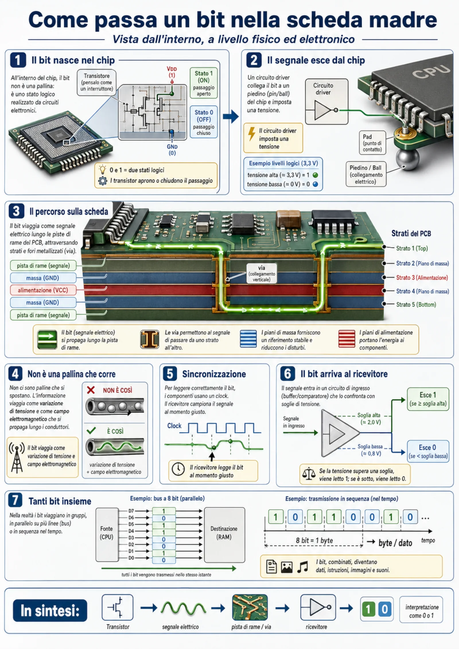
When we look at a motherboard, we see chips, connectors, copper traces and tiny components. We do not see data moving. That is why it is tempting to imagine a bit as a microscopic ball travelling from the CPU to memory. The picture is intuitive, but it is not what physically happens.
A bit is first of all a logical unit that can take one of two values: 0 or 1. The official NIST glossary defines it as a binary digit with a value of zero or one. Inside a circuit, however, those symbols are represented by measurable physical quantities, especially voltage levels, currents and changes in the electromagnetic field.
A bit is not a ball: it is a logical state
Saying that a circuit contains a bit does not mean that a material object called “zero” or “one” exists inside it. It means that the circuit is in one of two states allowed by its design. One voltage range is interpreted as a low level, therefore 0; another range is interpreted as a high level, therefore 1.
Real circuits use ranges rather than two perfect voltages. Electrical noise, voltage drops and small fluctuations always exist. A digital receiver does not require exactly 0.000 V or exactly 3.300 V. It compares the incoming signal with specified thresholds. The Texas Instruments Logic Guide distinguishes between input voltages guaranteed to be read as low or high and the levels produced by outputs.
These thresholds are not universal. They depend on the logic family, supply voltage and device. A 5 V example is useful for learning, but it does not describe every modern computer: many circuits operate at 3.3 V, 1.8 V or even lower voltages.
1. The bit originates inside the chip
Inside a processor or another integrated circuit, millions or billions of transistors are connected to form logic gates, registers, memories and processing units. In a simplified explanation, a transistor behaves like an electronically controlled switch. Intel's official overview explains how transistors are combined into logic gates and increasingly complex circuits.
When software executes an instruction, the processor changes the state of many internal nodes. At one of those nodes, a transistor network can pull the voltage towards a low or a high level. The node does not know whether it represents a number, a letter or a colour. It has only an electrical state. Meaning is created by the way hardware and software interpret the complete sequence of bits.
2. The output driver carries the signal to the package
The chip's internal signal is not connected directly to the motherboard. It first passes through an output circuit, usually called a driver. The driver must create a sufficiently stable electrical level for the receiving device and must charge and discharge the electrical capacitances of the connection.
From the driver, the signal reaches a chip pad and then the external package: pins, contacts or solder balls, depending on the package type. These parts provide the electrical connection between silicon and the circuit board. The bit remains information represented by a signal; the pin is simply the physical point through which that signal enters or leaves.
3. The journey continues along copper traces
On the motherboard, the connection continues along conductive copper traces. A modern board has several layers: some carry signals, while others are used as ground or power planes. Plated holes called vias allow a connection to move from one layer to another.
A trace is not an isolated little pipe. The signal and its return path form an electrical system. At high speed, trace geometry, reference-plane distance, impedance, discontinuities and interference become important. The official Texas Instruments high-speed layout guidelines explain why clock and fast data traces need careful design. Intel also provides educational material about signal integrity on printed circuit boards.
What actually moves?
Electrons in the copper do not instantly cross the whole board like cars on a road. When the driver changes state, it creates a change in voltage and electromagnetic field that propagates along the conductive structure. That propagation carries energy and information to the receiver.
For an introductory explanation, it is reasonable to say that “the electrical signal travels along the trace”. More precisely, the trace, its reference plane and the insulating material behave as a transmission line. This matters especially when signal edges are fast: reflections, noise and coupling can distort a signal even when the apparent data frequency seems modest.
4. The clock tells the receiver when to read
An electrical value must be read at the correct time. In synchronous systems, a clock provides a regular sequence of timing events. The receiver samples the data on a specified edge or within a timing window defined by the interface.
If the data arrives too late, changes too early or is disturbed at the sampling moment, it may be interpreted incorrectly. This is why designers consider setup time, hold time, timing margins and synchronisation. The clock does not magically turn voltage into a bit; it coordinates when the circuit must decide whether the level represents 0 or 1.
5. The receiver compares the signal with thresholds
At the end of the connection is an input circuit. It observes the received voltage and compares it with specified thresholds. A sufficiently low value becomes 0; a sufficiently high value becomes 1. Between the two guaranteed regions there may be an undefined interval where reliable behaviour is not promised.
The distance between actual output levels and required input thresholds contributes to the noise margin. A larger margin lets the system tolerate small disturbances without changing the interpreted value. This is why two components cannot be connected merely because they both use “zeros and ones”: their electrical levels must be compatible.
6. Bits travel in parallel or in sequence
Several bits may be transferred at the same time on several lines, as in a parallel bus, or one after another on the same line, as in serial communication. In both cases, the receiver sees an organised sequence of electrical states over time.
Eight bits commonly form one byte. NIST notes that a byte contains eight bits, but the meaning of that byte depends on context: it can represent part of a number, an encoded character, a colour value, a piece of an instruction or any other information defined by the system.
From signal to meaning
A motherboard does not see photographs, words or music. It sees transitions, levels, timing and sequences. Protocols, file formats and programs decide that a certain bit pattern must be understood as the letter “A”, a red pixel or an audio sample.
The journey can therefore be summarised as follows: a transistor network creates a state; a driver prepares it for transmission; the signal crosses the package, traces and vias; the receiver samples it and compares it with a threshold; finally, the system assigns meaning to the resulting sequence.
How to read the illustration correctly
The image used for this article is an educational map. It correctly shows the general chain — transistor, signal, trace, timing and receiver — but real platforms use different voltages, packages, protocols and board structures. Numerical values should therefore be read as examples, not as universal motherboard rules.
Frequently asked questions
Is a bit always represented by 0 V and 5 V?
No. Those values are a historical and educational example. Many modern circuits use lower supply voltages and different thresholds.
Does 1 always mean that a transistor is on?
Not necessarily. It depends on the observed node and the circuit topology. Some networks use active-low or inverted logic.
How fast does the signal travel?
Propagation is extremely fast but not instantaneous. It depends on connection geometry and board materials. In high-speed systems, fractions of a nanosecond can matter.
Why are ground planes needed?
They provide an electrical reference and a return path for signal current. A well-designed return path reduces interference and signal-integrity problems.